English
 Español
 Français
 Deutsch
What is the difference between InZennio Z41 and Z41 Pro/Lite?
Z41 Pro/Lite are the new models that replace InZennio Z41 in our catalogue from now on. The 3 devices are physically equal (excepting Z41 Pro/Lite include 2 analog-digital inputs), but starting from the application program version 2.2, Z41 Pro/Lite have been improved with new important functionality such as twelve general-purpose control pages, holiday calendar, water and gas monitor, four-byte indicators, new specific fan speed control, error log, light intensity regulation on RGB/RGBW controls... For further information, see the Z41 Pro or Z41 Lite manual.
Moreover, Z41 Pro allows IP connection for smartphone/tablet control with Z41 Remote app (available for iOS and Android) in the same way as InZennio Z41. However, dinamic IP is necesary for both devices to connect to IP network.
The application program available on the website is only valid for ETS4 or ETS5, is there a compatible version with ETS3?
No, the application program developed for the Z41 is only compatible with ETS4 or ETS5.
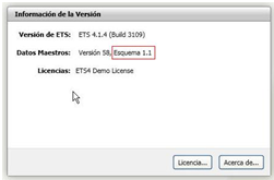
I cannot import the application program for the Z41, the ETS4 shows the message “The version of the Scheme is not valid", what can I do?
To import the application program for the Z41 is necessary to have the ETS4 software updated with a version of "Scheme" 1.1 or higher. You can view this information from the main screen of the ETS4, in the Overview section. The version information is displayed in the upper right corner.
May I install the Z41 horizontally?
Yes, from the Z41 Pro/Lite 2.3 versions and Z41 COM 1.1, this touch panels may be installed horizontally or vertically. On the other hand, InZennio Z41 can't be installed horizontally
May I use the KNX bus voltage (29VDC) as the additional power supply of the Z41?
No, the KNX bus voltage is not a clean signal as it is modulated by the data. This signal can cause a malfunction of the screen.
The KNX bus connector and the external power supply connector are opto-isolated to avoid potential interference with the KNX bus.
Do I need an additional KNX power supply as external power supply for the Z41?
No, the auxiliary power supply does not need to be a KNX power supply, a conventional power supply (12-29V DC), or the auxiliary output of some KNX power supplies is enough.
What is the total consumption of the Z41?
The consumption of the Z41 is divided as follows:
- KNX Bus: 6 mA
- External power supply: the maximum consumption at startup is 160 mA (with 12 V), 76 mA (with 24 V) or 64 mA (with 29 V), but in standby, its consumption is reduced to about half of this figure.
It can be checked in the Z41 datasheet
What is the firmware of the Z41?, and how can I update it?
We call firmware to the base software preloaded on the device that handles the display of all items on the screen. The firmware is independent of the ETS application program, but both must be the same version for the Z41 to work properly.
The firmware update must be performed via the miniUSB port or the Ethernet port:
- Via USB: using the adapter cable for USB firmware update connected to the mini-USB port placed on the back of the touch screen. The “.PAK” file for firmware update must be copied to the root folder of a USB flash drive.
- Via Ethernet: Downloading de Z41 Update tool and connecting the touch panel to be updated and the computer to the same local network. Z41 Lite cannot be updated via Ethernet
Both procedures are explained step by step in the firmware update manual
Should I update first the firmware or the software?
Even though it can be done in both ways, from Zennio we recommend to update firstly the firmware version, and secondly the application program.
The screen stays with blue background and it displays an “Error Software” message. What is going on?
The “Error Software” message means a wrong correspondence between Software and Firmware versions.
Software version X.Y must match with the firmware version X.Y.Z. The versions will be compatible when X.Y values are equal.
What is the Ethernet input for?
The Ethernet port built into the Z41 may be used to upgrade its firmware, and for the remote controlling of the Z41 via IP from devices such as smartphones or tablets.
How can I know the Z41 MAC number?
The MAC is displayed on the screen when the touch panel is in the firmware update state.
It is also possible to know it by running the command “arp-a” in the command shell (cmd) of a computer connected to the same network.
If a power failure occurs, do I need to re-set the date and time?
No, thanks to the button battery included in the Z41, the touch panel allows to keep the date and time data after a power failure.
When are the date and time of the Z41 sent to the BUS?
The Z41 Touch Panel only sends the date and time data to the BUS when these two options are set, more specifically when the SET button is pressed, at the end of the manual parameterization.
This feature allows synchronizing the date and time of the rest of Panels in the installation by creating two group addresses “Date” and “Time” to later link them with the appropriate communication objects in the rest of panels to synchronize; this way when adjusting date and time in one of the "master" panels, the rest of them will be also updated.
When having several touch screens Z41 in the same installation, How is recommended to configure the time/date sending period?
It is necessary to configure just one screen in the installation to send time and date periodically to the bus, disabling in the remaining devices the parameter “Time/Date Sending Period” that can be found at MAIN CONFIGURATION/ General.
What alphabets can be displayed on the Z41?
Z41 is able to show the following alphabets:
- Latin
- Greek
- Cyrillic
- Arabian
- Hebrew
- Chinese
- Japanese
Is it possible to disable the temperature and time displayed at the top of the screen?
Yes, it is possible to disable the display of this information through the GENERAL setting parameters independently.
Can I show a temperature value different from the one measured by the internal sensor in the header of the screen?
This is possible by enabling this option in the GENERAL setting parameters.
How can I display the values received in an indicator control over time?
It is possible to save a log of the values received in indicator controls of 1 or 2 bytes simply by enabling this option via the "Save Log?" parameter. Then, pressing on the indicator will open a pop-up window that will display graphically the values received in this indicator over time.
I have configured an “Energy Monitor” control to display the energy consumption and the objects that I need to link with my energy monitor do not appear. I can only see the objects “Energy Monitor: request” and “Energy Monitor: reset”, why?
To use this “Energy Monitor” control in Z41 Pro/Lite 1.1, it is necessary to enable the monitoring channels via the “Energy Monitor Objects” tab that you will find in the MAIN CONFIGURATION section. For each channel, four objects will be created: “Power”, “Energy”, “CO2” and “Cost Estimation”.
Starting from the 2.2 version, it is not necessary to enable the channels since these functions are enabled in each box configuration.
I have configured a 2-button control and the value sent by each button does not correspond to its icon. What’s happening?
When configuring the 2-button control, it must be taken into account that the icon selection parameter does not assign functionality to the button. The icon is independent of the value sent. All the 2-button controls have a parameter called "Action" that allows exchanging the value sent to the bus between the left and right buttons.
Why when playing Scene nº X, the Group Monitor always show a minor number X-1?
This is due to the particular structure of the "Scenes Control" DPT. For further information, consult the Scenes Example Project.
How many Group Addresses do I need to work with Scenes?
One only Group Address will be needed to work with scenes.
Every device involved in the Scene has a specific Communication object "Scenes". It will only be necessary to link this with the "Scenes" Communication Objects in the devices involved in the predefined atmosphere. For further information, consult the Scenes Example Project.
Is it possible to show the current scene in the display?
Scenes are events, not status; while setting a scene, some predefined parameters are set in the devices involved in the same, however these can be later modified by the users.
How can I learn scenes with the display?
Guess a user defines the "Scene Night" (programming the Panel with parameters and group addresses via ETS) to:
- Turn all the lights Off
- Turn Off the Heating and the AC system
- Activate the Alarm System
Once the scene is defined, every time we play it, a predefined atmosphere is generated.
Afterwards, the user wants this configuration instead:
- Turn all the lights Off except one (the one to remain ON, will be a guiding light)
- Turn Off the Heating and the AC system
- Activate the Alarm System
The way to do this is:
1. Run the scene to be modified.
2. Turn the light we want it to be the guiding light On.
3. Just save the new scene into the Panel by keeping a long press (3 seconds) on the original scene "Run" button.
THIS PROCESS REPLACES THE ORIGINAL SCENE BY THE MODIFIED ONE
I have several scenes scheduled to be launched at the same time and only one is launched, why?
Due to the fact that the scene object is unique to the entire touch panel, it is only possible to launch one scene at a time, more precisely, the scene launched will be the one set in the last box of the last page. To avoid this effect, the sending of the scenes can be shifted in time.
How can I schedule a Climate System timer?
1. Configure one Z41 box as "chronothermostat" (Visualization: Other --> Function: Chrono-thermostat)
2. Three group objects will be generated:
- [Px][By] Chrono-thermostat: enabling - Link to a binary object to enable/disable the chronothermostat function
- [Px][By] Chrono-thermostat: temperature setpoint - Link to the thermostat setpoint object
- [Px][By] Chrono-thermostat: on/off - Link to the thermostat on/off object
Note: it is not obligatory to link these 3 group object if you don't want to control any of these functions by means of chronothermostat
3. In the corresponding Z41 box, set the time and setpoint to which you want to set the climate system
Is it possible to do a presence simulation with Z41?
Z41 does not have that specific function; however, a similar functionality can be created by programming weekly and daily timers, and setting different sequences to simulate presence. In addition, Z41 allows users the remote control through smartphone and tablet, having the full control of the installation.
What is the Technical Alarm Cyclical Monitoring used for?
This function allows a critical alarm system monitoring (i.e. gas sensor) to check its proper working in the installation.
In this case, the function waits for a value reception to confirm that the system is working properly. If this value is not received within the specific time parameterized in the ETS, the alarm goes off warning users of a possible problem in the device.
Climate "MODE" Communication object structure in Z41 Touch Panel.
This communication objet (DPT_HVACContrMode_20.105) fulfillls the KNX standard with the following structure:
0 = AUTO
1 = HEAT
3 = COOL
9 = FAN
14 = DRY
This DPT structure is actually implemented in all the Zennio devices. This way, all the devices can be integrated together in an installation, as their Communication Objects structure is identical. For further info, please contact our Technical Department.
What is the Special Mode control of the Z41 for?
The Special Mode control is used to set pre-configured setpoints in the thermostat. For further information about this functionality, see the manual of the “Building” thermostat.
Can I restrict the setpoint temperatures in public buildings with the Z41?
Yes, the Z41 temperature controls allow restricting the range of allowed values.
The internal temperature sensor of the Z41 shows a higher temperature value than the real one, Why?
The Z41 usually gets hot during its programming in such a way that the real temperature is distorted during this time period. The Z41 will recover the real temperature once it returns to its standby status.
Furthermore, supplying the Z41 with a voltage value or another can cause variations in the measurement of the temperature; however, the temperature displayed is automatically calibrated by selecting the “Power Supply Voltage” parameter properly.
Additionally, the internal temperature sensor can be calibrated manually from the ETS setup or from the configuration page.
Can the temperature measured by the internal sensor of the Z41 be sent periodically to the bus?
Yes, within the parameters of the Z41, it is possible to choose a cyclic sending period of the temperature measured by the internal sensor with a range between 10 and 1000 s.
What kind of thermostatic control does Building Thermostat allow?
In Building Thermostats, the following types of thermostatic control can be configured:
- PI Continuous
- PI PWM
- 2 Points with Hysteresis
What kind of thermostatic control can I use with my climate system?
In a radiators system, thermostat acts over the valves of radiators, which control the hot water circulation through the radiator. If the valves are closed, the hot water from the boiler does not circulate through radiators and after a time they stop radiating heat to ambient. The valves can be:
- Two-points valve (open/close), which can be controlled with 2 Points with Hysteresis or PI-PWM thermostat.
- Motorized valve (percentage), which can be controlled with PI-Continuous thermostat
In radiant floor systems, the thermostat control acts over the valves in the collector return, in the same way that it is done in radiators system. Thus, the same kinds of thermostatic control can be used for radiant floor valves.
In a Fan Coil system, there are two elements to control: valves that allow the water flow through the pipes of the Fan Coil and the fan speed. If a thermostatic control over the valves is carried out, 2 Points with Hysteresis or PI-PWM controls can be used. If the thermostatic control should be applied over fan speed, PI-Continuous control will be the most suitable one.
In zoning systems, a 2 Points with Hysteresis or PI-PWM control acts over the grilles of the different rooms and lets the air of the pump duct get into these rooms until the real temperature in each room reaches its corresponding setpoint.
The PI thermostat demands heat/cool when the real temperature has already reached the setpoint or it does not demand heat/cool when setpoint has not been reached.
When the thermostat performs a PI thermostatic control, the objective is making the real temperature achieve the setpoint temperature, established by user. The PI thermostat calculates the difference between current real temperature and setpoint temperature (proportional part) and also the variation of real temperature during the time that thermostat is activated (integral part). For a correct functioning of the thermostat with a certain climate system, the following characteristics should be bear in mind:
- K and T parameters should be configured according to the climate system that the thermostat is controlling. This way, the thermostat will have into account the thermal inertia of the climate system when calculating the control value.
- Cycle Time for PI control should be selected regarding the thermal inertia of the climate system. The higher the thermal inertia of the climate system is, the longer Cycle Time for PI the thermostat should have.
If these parameters (K, T and Cycle Time) are not correctly selected, the climate system is not responding to thermostat control as expected.
- The climate system should be correctly dimensioned and there should not be an external source of heat/cool different that the climate system. Otherwise, the climate system response to thermostat heat/cool demand could not be the expected and, thus, the thermostat control can be influenced.
For example: a heating system that is under-dimensioned (or it is well dimensioned but the window is open) will not heat as much as the thermostat expects regarding the K and T parameters. The thermostat will calculate a heat demand that the climate system cannot provide. Since the variation of the real temperature is lower than expected, the thermostat will increase the integral part and it will demand more heat. The result is that the climate system takes too long to reach the setpoint temperature and the real temperature will rise several degrees above the setpoint instead of maintaining this temperature.
What is the range of Setpoint Temperature in Building Thermostat?
Zennio Home Thermostat admits Setpoint Temperatures between -20ºC and 95ºC.
Can the thermostat use the temperatures collected from two different temperature probes as reference temperature?
Yes, indeed, when a room is large enough, the temperature can vary in the different sides and it is desirable to collect the temperature from two sources and combine them in one of the following proportions:
- Proportion [75%(1) - 25%(2)]
- Proportion [50%(1) - 50%(2)]
- Proportion [25%(1) - 75%(2)]
Where (1) is the temperature collected from the temperature source 1 and (2) the temperature collected from the temperature source 2.
The KNX controller in installation sends relative Setpoint Temperatures, can I use Zennio Thermostat?
Zennio Building Thermostat allows relative setpoint temperatures, which sets a variation in the setpoint temperature of the active Special Mode, with an Offset. An absolute value of Offset (ºC) can be established with object [Tx]Setpoint Offset or Offset can be incremented or decremented 0.5ºC with [Tx]Setpoint Step.
This way:
Setpoint Temperature = Basic Setpoint + Special Mode Offset + Setpoint Offset (variable)
How can I make the thermostat work in Freezing protection mode?
Once the setpoint temperature of the Protection Special Mode is set for Heating Mode in ETS parameters, it works automatically. Whenever the real temperature (reference temperature ot the thermostat) is below the Protection setpoint temperature for Heating Mode, the Heating Control Variable is activated, regardless the thermostat is ON or OFF.
For example: when the Protection setpoint temperature in Heating Mode is 10ºC, the thermostat will send 1 if thermostat is type 2 points with hysteresis or PI-PWM, or 100% if thermostat is PI-Continuous, through the object Heating Control Variable, regardless the thermostat is ON or OFF, whenever the real temperature is below 10ºC.
How can I make the thermostat work in Overheating protection mode?
Once the setpoint temperature of the Protection Special Mode is set for Cooling Mode in ETS parameters, it works automatically. Whenever the real temperature (reference temperature ot the thermostat) is above the Protection setpoint temperature for Cooling Mode, the Cooling Control Variable is activated, regardless the thermostat is ON or OFF.
For example: when the Protection Setpoint for Cooling Mode is 35ºC, the thermostat will send 1 if thermostat is type 2 points with hysteresis or PI-PWM, or 100% if thermostat is PI-Continuous, through the object Cooling Control Variable, regardless the thermostat is ON or OFF, whenever the real temperature is above 35ºC.
What are the special modes?
In Zennio Building Thermostat, the Special Modes are Thermostat Statuses, so that the setpoint for the corresponding Special Mode is established as setpoint in thermostat, but this thermostat setpoint can be changed to fit the user needs.
When the thermostat is OFF, depending on parameter “Automatic ON when a new special mode arrives” in thermostat configuration, it will behave as follows:
- If it is enabled, the thermostat will turn on when a Special Mode is triggered.
- If it is disabled, the thermostat will remain OFF even if a Special Mode is triggered.
How could I know which Special Mode is active?
In Building Thermostat, the active Special Mode can be known through a 1byte object of status [Tx] Special Mode Status.
What is the effect of a setpoint change when a Special Mode is active?
In Building Thermostat, there is always one active special mode:
- Absolute Setpoints: the special mode is maintained if the new setpoint is in the temperature band limited by other special modes setpoints. In case the new setpoint is above or below other special mode setpoint, this special mode is activated.
- Relative Setpoints: the thermostat setpoint is modified but the same Special Mode is maintained. If the setpoint change is due to a change in Basic Setpoint, all the setpoints of Special Modes will be modified. If the change is due to a change in Offset, it will affect to all the Special Modes only if the parameter “Permanently apply change to basic setpoint shift” is enabled. Otherwise, it will only affect to the currently active Special Mode.
Could the setpoint temperatures of the Special Modes be sent to KNX Bus?
When a Special Mode is set, the thermostat setpoint temperature will be updated with the corresponding setpoint of the Special Mode and the thermostat setpoint status will be sent to KNX bus. However, there are not communication objects associated to the setpoints of the Special Modes, so they cannot be read.
How can I select the default values of the setpoint of the Special Modes?
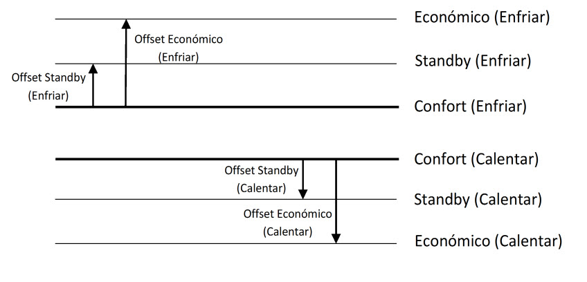
In Building Thermostat, the setpoint temperatures of the Special Modes by default can be selected in the thermostat parameters, with the absolute setpoint of Comfort Mode as a reference and the Offset of the rest of Special Modes.
How can I change the setpoint of a Special Mode?
In Building Thermostat with absolute setpoint, the setpoint of the Special Modes can only be modified if “Permanently apply change to special mode setpoint” is enabled. In this case, before activating the new Special Mode, the current thermostat setpoint is stored as setpoint of the current Special Mode. The setpoint of the special modes can be reset to initial parameterized values, through the Setpoint Reset object. It is also important that the setpoints for Comfort mode cannot be stored if they are below the default setpoint for Comfort in Cooling mode or above the default setpoint for Comfort in Heating mode.
In case “Permanently apply change to special mode setpoint” is disabled, a change in thermostat setpoint is kept until a change of Special mode, but it will not be stored.
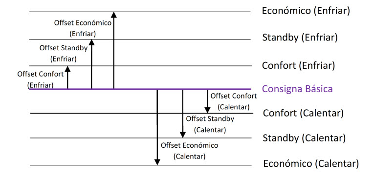
In Building Thermostat with relative Setpoints: the setpoints of Special Modes are established with an Offset of Special Mode with Basic Setpoint as reference. If this Basic Setpoint is modified, the setpoints of all the Special Modes will be altered in the same way. The setpoint temperature when a Special Mode is activated will be the default setpoint of the Special Mode in ETS configuration plus the variable Offset value, which is set through the communication object. This variable Offset will affect all the Special Modes if the parameter “Permanently apply change to basic setpoint shift” is enabled. Otherwise, it will only affect to the currently active Special Mode and it will reset (Offset=0) with the Special Mode change.
Offset variation has two important characteristics that should be taken into account:
- The Offset value that can be added to default setpoint will be limited by upper and lower limits, defined in ETS parameterization.
- The Offset change affect to setpoint temperature of the Special Mode in the opposite working mode (Heating or Cooling), so that the automatic change of mode is carried out properly.
How can I synchronize the setpoint temperatures of a Special Mode in different thermostats?
In Building Thermostat with relative setpoints, all the thermostat should have the same parmeters for the offset of Special Modes.
In case “Permanently apply change to basic setpoint shift” is enabled, the setpoint temperatures of the Special Modes can be synchronized with a central control of Basic Setpoint (with objects [Tx]Basic Setpoint) and Offset (with objects [Tx]Setpoint Offset). Otherwise, a central control of Reset (with objects [Tx] Offset Reset) would be needed to set the default Offsets.
In Building Thermostat with absolute setpoints, all the thermostat should have the same parmeters for the setpoints of Special Modes. This way they can be synchronized to default values with objects [Tx]Setpoint Reset, that set de default setpoints.
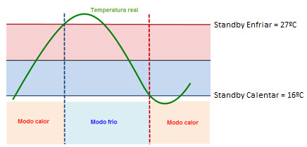
My thermostat changes between Cooling and Heating mode when I activate a Special Mode
In Building Thermostat, values of setpoints of special modes have a limitation: Comfort, Standby and Economy setpoints should be established according to bands. In addition, the automatic change of mode is caused by variation of real temperature compared with setpoint temperatures of the current Special Mode in Heating and Cooling mode. This avoids undesired automatic changes of mode when a special mode or setpoint temperature changes.
My thermostat always uses 25 ºC as the reference temperature.
The Building thermostat module is independent of the device and it does not use the value measured by the internal temperature probe as the reference temperature by default. It is necessary to create one group address to link the “Temperature Source” object of the thermostat to the sending object of the internal temperature probe or other KNX probe.
Is it possible to establish more than one security code in the Z41?
It is possible to protect any page of the Z41 from an unauthorized access. Up to two security levels can be configured
What is the welcome object for?
The welcome object can be used to send a binary value to the bus or to launch a scene, the first time that the touch panel is pressed after a configurable time of inactivity. This object can be very useful to turn a light on or to launch a welcome scene.
What is the locking for?
The lock object allows enabling or disabling the touch area of the Z41, so that if the screen is locked, it ignores any press on it until it is unlocked. This object may be useful to disable touch panels installed in public areas.
Can the Z41 PRO be controlled by using an infrared remote controller?
No. It is possible to use the built-in Ethernet port for the remote controlling of the touch panel via IP from devices like smartphones, tablets, personal computers, …
Can I control my Z41 PRO from my smartphone or tablet?
Yes, it is possible to control your Z41 from your smartphone or tabled with Android or iOS.
Is it possible to receive Z41 PRO notifications in my smartphone or tablet?
Push notifications are available in your smartphone and tablet paired with your Z41
A push notification will be received when an alarm event takes place in your installation:
- Alarm activation
- Alarm confirmation
- Alarm deactivation
For a proper notifications reception, your smartphone or tablet must be paired with the touch panel Z41 and the Z41 Remote App must be updated to the latest version.
Is it possible to use Z41 PRO as a KNX-IP interface for programming or monitoring?
No, it is necessary to use a KNX-IP Interface or KNX-IP Router. The Z41 IP connection is to control it remotely from any iOS or Android device and to update the firmware.
How can I control Z41 PRO remotely using my Smartphone or Tablet?
To control properly your Z41 through the Z41 Remote app, the following requirements must be satisfied:
- To enable the remote control function under Z41 parameters:
- MAIN CONFIGURATION / Ethernet / Remote control through the Internet
- CONFIGURATION PAGE/Configuration/Device Pairing
- To install the application Z41 Remote in your Smartphone or Tablet (Android & iOS)
- To enter the pairing code provided by Z41 in the corresponding box in Z41 Remote.
- Take into account that the touch panel must be connected to the network by using a wired connection which has not a previous wireless section.
Can I control my Z41 PRO from a Smartphone or Tablet connected to the same local network but without access to Internet?
Yes. After pairing the Z41 and the Smartphone through the Internet, it can be controlled by means of a Local Area Network (LAN). Both devices should be connected to this LAN. Notice that only the Internet connection is needed during the pairing. Then, it is controlled by LAN
Differences between versions
The following table shows the most significant functionalities of each version and their differences.
| Functionality | Z41 1.x | Z41 2.x | Z41 3.0 |
| General-purpose pages | 2 | 6 (***) | 6 (***) |
| Specific-purpose pages (climate, scenes, timers) | 4 | ||
| Binary indicators (text / icon) | | ||
| Enumerated indicators (text / icon) | |||
| Numerical indicators (percentage, floating point, etc.) | |||
| Chronological data log for numerical indicators | |||
| 1-button controls (binary, scene, percentage, floating point, etc.) | |||
| 2-button controls (binary, scene, percentage, floating point, etc.) | |||
| Climate controls | |||
| RGB controls | |||
| RGBW controls | |||
| Energy consumption monitoring | |||
| Daily timers | 48 (*) | 48 (*) | |
| Weekly timers | 16 | 48 (*) | 48 (*) |
| Alarms | 8 | 48 (*) | 48 (*) |
| Alarm log | |||
| Control from remote IP applications |
(*) As a maximum (making use of all boxes from all pages).
(**) Only positive numeric values.
(***) This differentiation does not apply anymore; six pages are now provided combining all the functionalities together.
What does safe mode mean?
When a device is running in safe mode the programming LED blinks in red, meaning that the application program is halted.
How to set a device in safe mode?
To activate the safe mode, keep the programming button pressed while connecting the device into the KNX bus. This process is described in the datasheet of the device.
How to exit from safe mode?
To exit from safe mode, simply plug the KNX bus into the device but do not press the programming button this time. This way the programming LED does not blink, meaning that the application program is running (safe mode is not active).
How do a download in safe mode?
When an incidence is caused during the download, it is recommended to do a safe mode download, to ensure that the previous corrupted download doesn’t affect to this new download:
To do a download in safe mode, you should follow the next steps:
- Disconnect the device from KNX bus.
- Connect the device to KNX bus while holding down the programming button. The programming LED will start blinking indicating that the device is in safe mode.
- Once in safe mode, download the application program completely to the device.
- When the download is finished, disconnect and reconnect the device from the bus.