English
 Español
 Français
 Deutsch
Differences between ZAS and Roll-ZAS
Inputs:
ZAShas 2 opto-coupled inputs that can be configured individually as a switch / sensor or a temperature probe.
Roll-ZAS adds the possibility of connecting Zennio motion sensors, model ZN1IO-DETEC, in addition to the ZAS settings.
Screensaver:
ZAS only admits that the temperature displayed on the screensaver page is measured by the incorporated internal sensor.
Roll-ZAS allows selecting the source of temperature of which measurement is going to be displayed on the screen saver page, this source may be the internal sensor or an external value.
Buzzer:
Roll-ZAS provides two communication objects to act on the buzzer built into the touch panel. These objects can be enabled / disabled the sound (beep) produced when acting on the buttons or use the sound for other purposes.
Thermostat:
ZAS has a thermostat “home”included in the thermostat submenu of the device.
Roll-ZAS has 2 thermostats "building", the operation of which is independent of the device, so it can be commanded by Roll-ZAS itself or by other device through the KNX bus.
Menus / Pages:
ZAS has some functionality accessible through the submenu pages in the display. These pages are: thermostat, scenes, presence simulation, security, configuration and indicators.
In Roll-ZAS, submenu pages of thermostat, scenes and simulation of presence, disappear. In return, Roll-ZAS has 4 pages that will let the user assign different functionality to the buttons of the touch panel according to the selected page in the display. This adds the option to configure up to 32 controls per device, which can be clima, scene or timer controls. Moreover, security and configuration pages are also available. To navigate through the pages you can enable the arrow buttons on the panel.
Functionality of the buttons:
Roll-ZAS adds new controls, specifically:
- Couples of buttons:
- Switch + Indicator
- Multimedia Control (only on page 4): this control is associated with an object "String Indicator" that allows to display a chain of up to 14 characters, for example, the title of a song.
- Individual buttons:
- Dimmer
- Timer
To see how these and other controls included in the Roll-ZAS work, take a look at the manual of the device.
Icons:
Roll-ZAS includes the ability to associate icons to buttons to be shown on the display for an easier interpretation of its operation.
Touch button LED:
Roll-ZASextends the customization options of the LEDs of the buttons behavior for both, couple and individual controls.
- Pair buttons:
- Regular: LED on during some seconds when the button is pressed
- State-dependent: the LED of the button will light while the object status is “1” and it will remain switched off when the object status is “0”.
- State-dependent (both LEDs). (New in Roll-ZAS)
- Individual buttons: (New in Roll-ZAS)
- Regular.
- State-dependent.
Arrow buttons:
With ZAS, it is possible to configure the pair of arrow-shaped buttons to perform a temperature control, for example, to set the setpoint of the thermostat.
With Roll-ZAS, this configuration is not possible and you should set the temperature control through a couple of touch buttons. In Roll-ZAS these arrow buttons can be configured to navigate through the pages on the display.
Security:
ZAS supports password protection for menus and buttons from the Security submenu. Only 1 password per device is supported.
Roll-ZAS allows 2 hierarchical levels of security for the protection of whole pages, 2 passwords per device. From the security page you can change the security level of each page.
For further information, please read the specific manual of each application program:
Which Zennio devices include binary inputs?
You can check which Zennio devices have binary (digital) inputs in the following table
Differences between Push button and Switch/Sensor inputs
A push button connected to an input consists of a device, which allows, or not, the current flow while this is being pushed; in normal conditions, push buttons contacts are always open (NO) or closed (NC). This event is a pulsation and the time it lasts, threshold time. Depending on the “Threshold Time” it can be distinguished two different actions:
- Short press
- Long press
A Switch/Sensor connected to an input, consists of an electrical mechanism which may have its contacts open or closed under normal conditions. These mechanisms don’t recover their normal position automatically as with the push button. A transition of a digital signal from low/high/low is called "Edge".
- Falling edge: Closed contact to Open Contact.
- Rising edge: Open contact to Closed Contact.
What type of contacts can be connected on the binary inputs?
Binary inputs of Zennio devices are voltage free contacts. They can be individually configured and each of them can be connected to a push buttons and/or a switch/sensors.
Can I connect several push buttons in parallel in the same input?
Yes, inputs are voltage free, so there is no problem in connecting several push buttons in parallel.
Why do I have to press twice over an input for the output to react?
It happens when one output is commuted by two or more different inputs and the output status object isn't used to synchronize these inputs.
What is the maximum length allowed for the wiring of the digital inputs?
The wiring of the digital inputs can be extended up to 30 meters using a cable with a section between 0.15 mm2 and 1 mm2.
What is the difference between motion detectors P (ZN1IO-DETEC-P) and X (ZN1IO-DETEC-X)?
The only difference is that the motion detector P has a built-in luminosity sensor and it allows to constraint the detection based on the luminosity level detected in the room. The motion detector X has no luminosity sensor.
Can I connect a motion sensor different from DETECT-P/X to an device input configured as motion sensor?
Zennio devices with inputs configurable as sensor motion have been designed to work together with the motion sensor DETEC-P and DETEC-X
We can’t guarantee the proper working of a different motion sensor connected to a Zennio device input configured as motion sensor, thus, when using a different motion sensor, the input must be configured as binary switch, and the sensor motion must send the detection using a free potential contact.
To which Zennio devices can I connect a motion detector?
Motion detectors can be connected to Zennio devices with analog-digital inputs.
If you do not know if your Zennio device allows the motion detector connection, just look into the following table. For further information, consult the product datasheet.
If the device allows the connection of a motion sensor, at its website tools section you will find the motion sensor manual.
How can I know the position where the micro switch must be placed (Type A/B)?
Depending on the device where the motion sensor is connected, the micro switch must be placed at the position A or B. To know which position corresponds to your device, it is necessary to check the device datasheet to which the motion sensor will be connected.
How many sensors can I connect into the same input?
Up to two different sensors can be connected in parallel to the same motion sensor input, as long as at least one of them has the luminosity sensor switch in the OFF position. This is achieved using the micro-switch located on the back of the device. For further information please refer to the motion sensor datasheet.
Do I need an external power supply for the sensor?
No, you just need to connect it to the inputs of the devices allowing its control
What is the detection area covered by a Zennio motion sensor?
This feature depends critically on the location of the device. In particular, for a detector located in the ceiling of a room, the detection area can be doubled if you double the height at which it is placed. For further information, consult the motion sensor datasheet.
How should I install the motion sensor to get the most of its functionality?
In the Motion Sensor area, you can download the Installation Note that includes installation tips to find the most suitable place to be placed.
How is the luminosity level measured by the sensor sent to the bus? (Only ZN1IO-DETEC-P)
The sensor sends a luminosity level in the range [1.....100] through a 1 byte Communication Objet. In any case this is a a 2 bytes object with the value measured in LUXES.
Can we cancel the LED blinking everytime there is a detection?
Yes, using the micro switch at the rear of the device.
What is the maximum length allowed for the wiring of the analogue inputs?
The wiring of the analogue inputs can be extended up to 30 meters using a cable with a section between 0.15 mm2 and 1 mm2.
The luminosity sensor does not measure correctly. (Only ZN1IO-DETEC-P)
Check if the microswitch number 2 is placed in the correct position. You can find this information in the data sheet of the device to which it is connected.
To which Zennio devices can I connect a temperature probe?
Temperature probes can be connected to Zennio devices with analog-digital inputs. To know if a device has analog-digital inputs, look into its datasheet.
In the following table you can check all Zennio devices with analog-digital inputs
What is the max cable length of the temperature probes?
The probe cable length provided by Zennio is 1.5 meters, however, this can be enlarged by means of a cable with similar characteristics up to a maximum of 30 meters.
What is the resistance value of the temperature probe at 25°?
The resistance value at 25°C is 6,8 kΩ
What are the valid measurement ranges for the temperature probes?
The following ranges are valid for the probes:
- Epoxi probe: [-30ºC........+90ºC]
- Steel probe: [-30ºC........+125ºC]
What is the appropriate probe in my installation?
It depends on the desired temperature range and the place where the probe will be placed.
As described in the previous question, steel probes have a broader range of measurement and are ready to work in more extreme environments than epoxy probes.
What is the temperature probe precision when it is used in QUAD?
It has a precision of +/- 0,5 °C
Can I use temperature probes different from the supplied by Zennio?
Zennio devices were designed to operate according to the characteristics of our temperature probes. We can only guarantee the proper working of the device with Zennio probes.
Exceptionally, other NTC temperature probes can be used with RailQUAD and QUAD Plus (from version 1.1 of both devices) since it is possible to configure the parameters of the characteristic curve of a NTC probe in this application program
How can I install a temperature probe into a narrow plastic pipe?
Use a T-shaped piece, take advantage of the new outlet to install a thermowell and now you will be able to place inside our steel temperature probe ZN1AC-NTC68S.

How can I hide the ambient temperature probe on the wall?
Install a conventional mounting box and uses a cable outlet cap. Place the temperature probe so that only its measuring end is seen. In this case we recommend using our epoxy resin probes ZN1AC-NTC68E and ZN1AC-NTC68F.
Moreover, SQ-AmbienT has been designed to meeting this need, a temperature probe installed in a Square family panel that provide an minimalistic aesthetic to the installation
What kind of thermostatic control does Building Thermostat allow?
In Building Thermostats, the following types of thermostatic control can be configured:
- PI Continuous
- PI PWM
- 2 Points with Hysteresis
What kind of thermostatic control can I use with my climate system?
In a radiators system, thermostat acts over the valves of radiators, which control the hot water circulation through the radiator. If the valves are closed, the hot water from the boiler does not circulate through radiators and after a time they stop radiating heat to ambient. The valves can be:
- Two-points valve (open/close), which can be controlled with 2 Points with Hysteresis or PI-PWM thermostat.
- Motorized valve (percentage), which can be controlled with PI-Continuous thermostat
In radiant floor systems, the thermostat control acts over the valves in the collector return, in the same way that it is done in radiators system. Thus, the same kinds of thermostatic control can be used for radiant floor valves.
In a Fan Coil system, there are two elements to control: valves that allow the water flow through the pipes of the Fan Coil and the fan speed. If a thermostatic control over the valves is carried out, 2 Points with Hysteresis or PI-PWM controls can be used. If the thermostatic control should be applied over fan speed, PI-Continuous control will be the most suitable one.
In zoning systems, a 2 Points with Hysteresis or PI-PWM control acts over the grilles of the different rooms and lets the air of the pump duct get into these rooms until the real temperature in each room reaches its corresponding setpoint.
The PI thermostat demands heat/cool when the real temperature has already reached the setpoint or it does not demand heat/cool when setpoint has not been reached.
When the thermostat performs a PI thermostatic control, the objective is making the real temperature achieve the setpoint temperature, established by user. The PI thermostat calculates the difference between current real temperature and setpoint temperature (proportional part) and also the variation of real temperature during the time that thermostat is activated (integral part). For a correct functioning of the thermostat with a certain climate system, the following characteristics should be bear in mind:
- K and T parameters should be configured according to the climate system that the thermostat is controlling. This way, the thermostat will have into account the thermal inertia of the climate system when calculating the control value.
- Cycle Time for PI control should be selected regarding the thermal inertia of the climate system. The higher the thermal inertia of the climate system is, the longer Cycle Time for PI the thermostat should have.
If these parameters (K, T and Cycle Time) are not correctly selected, the climate system is not responding to thermostat control as expected.
- The climate system should be correctly dimensioned and there should not be an external source of heat/cool different that the climate system. Otherwise, the climate system response to thermostat heat/cool demand could not be the expected and, thus, the thermostat control can be influenced.
For example: a heating system that is under-dimensioned (or it is well dimensioned but the window is open) will not heat as much as the thermostat expects regarding the K and T parameters. The thermostat will calculate a heat demand that the climate system cannot provide. Since the variation of the real temperature is lower than expected, the thermostat will increase the integral part and it will demand more heat. The result is that the climate system takes too long to reach the setpoint temperature and the real temperature will rise several degrees above the setpoint instead of maintaining this temperature.
What is the range of Setpoint Temperature in Building Thermostat?
Zennio Home Thermostat admits Setpoint Temperatures between -20ºC and 95ºC.
Can the thermostat use the temperatures collected from two different temperature probes as reference temperature?
Yes, indeed, when a room is large enough, the temperature can vary in the different sides and it is desirable to collect the temperature from two sources and combine them in one of the following proportions:
- Proportion [75%(1) - 25%(2)]
- Proportion [50%(1) - 50%(2)]
- Proportion [25%(1) - 75%(2)]
Where (1) is the temperature collected from the temperature source 1 and (2) the temperature collected from the temperature source 2.
The KNX controller in installation sends relative Setpoint Temperatures, can I use Zennio Thermostat?
Zennio Building Thermostat allows relative setpoint temperatures, which sets a variation in the setpoint temperature of the active Special Mode, with an Offset. An absolute value of Offset (ºC) can be established with object [Tx]Setpoint Offset or Offset can be incremented or decremented 0.5ºC with [Tx]Setpoint Step.
This way:
Setpoint Temperature = Basic Setpoint + Special Mode Offset + Setpoint Offset (variable)
How can I make the thermostat work in Freezing protection mode?
Once the setpoint temperature of the Protection Special Mode is set for Heating Mode in ETS parameters, it works automatically. Whenever the real temperature (reference temperature ot the thermostat) is below the Protection setpoint temperature for Heating Mode, the Heating Control Variable is activated, regardless the thermostat is ON or OFF.
For example: when the Protection setpoint temperature in Heating Mode is 10ºC, the thermostat will send 1 if thermostat is type 2 points with hysteresis or PI-PWM, or 100% if thermostat is PI-Continuous, through the object Heating Control Variable, regardless the thermostat is ON or OFF, whenever the real temperature is below 10ºC.
How can I make the thermostat work in Overheating protection mode?
Once the setpoint temperature of the Protection Special Mode is set for Cooling Mode in ETS parameters, it works automatically. Whenever the real temperature (reference temperature ot the thermostat) is above the Protection setpoint temperature for Cooling Mode, the Cooling Control Variable is activated, regardless the thermostat is ON or OFF.
For example: when the Protection Setpoint for Cooling Mode is 35ºC, the thermostat will send 1 if thermostat is type 2 points with hysteresis or PI-PWM, or 100% if thermostat is PI-Continuous, through the object Cooling Control Variable, regardless the thermostat is ON or OFF, whenever the real temperature is above 35ºC.
What are the special modes?
In Zennio Building Thermostat, the Special Modes are Thermostat Statuses, so that the setpoint for the corresponding Special Mode is established as setpoint in thermostat, but this thermostat setpoint can be changed to fit the user needs.
When the thermostat is OFF, depending on parameter “Automatic ON when a new special mode arrives” in thermostat configuration, it will behave as follows:
- If it is enabled, the thermostat will turn on when a Special Mode is triggered.
- If it is disabled, the thermostat will remain OFF even if a Special Mode is triggered.
How could I know which Special Mode is active?
In Building Thermostat, the active Special Mode can be known through a 1byte object of status [Tx] Special Mode Status.
What is the effect of a setpoint change when a Special Mode is active?
In Building Thermostat, there is always one active special mode:
- Absolute Setpoints: the special mode is maintained if the new setpoint is in the temperature band limited by other special modes setpoints. In case the new setpoint is above or below other special mode setpoint, this special mode is activated.
- Relative Setpoints: the thermostat setpoint is modified but the same Special Mode is maintained. If the setpoint change is due to a change in Basic Setpoint, all the setpoints of Special Modes will be modified. If the change is due to a change in Offset, it will affect to all the Special Modes only if the parameter “Permanently apply change to basic setpoint shift” is enabled. Otherwise, it will only affect to the currently active Special Mode.
Could the setpoint temperatures of the Special Modes be sent to KNX Bus?
When a Special Mode is set, the thermostat setpoint temperature will be updated with the corresponding setpoint of the Special Mode and the thermostat setpoint status will be sent to KNX bus. However, there are not communication objects associated to the setpoints of the Special Modes, so they cannot be read.
How can I select the default values of the setpoint of the Special Modes?
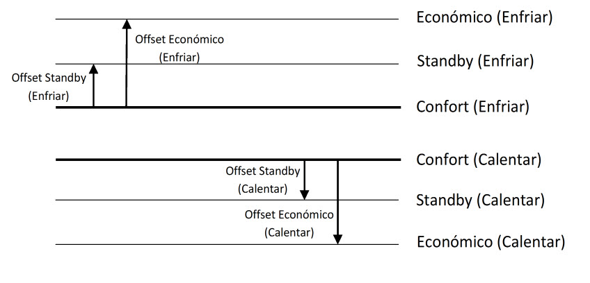
In Building Thermostat, the setpoint temperatures of the Special Modes by default can be selected in the thermostat parameters, with the absolute setpoint of Comfort Mode as a reference and the Offset of the rest of Special Modes.
How can I change the setpoint of a Special Mode?
In Building Thermostat with absolute setpoint, the setpoint of the Special Modes can only be modified if “Permanently apply change to special mode setpoint” is enabled. In this case, before activating the new Special Mode, the current thermostat setpoint is stored as setpoint of the current Special Mode. The setpoint of the special modes can be reset to initial parameterized values, through the Setpoint Reset object. It is also important that the setpoints for Comfort mode cannot be stored if they are below the default setpoint for Comfort in Cooling mode or above the default setpoint for Comfort in Heating mode.
In case “Permanently apply change to special mode setpoint” is disabled, a change in thermostat setpoint is kept until a change of Special mode, but it will not be stored.
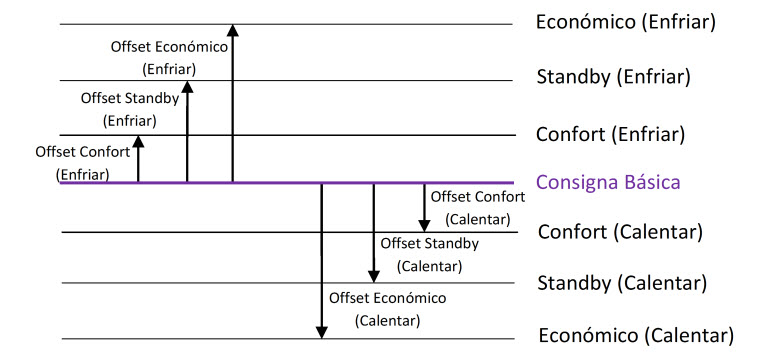
In Building Thermostat with relative Setpoints: the setpoints of Special Modes are established with an Offset of Special Mode with Basic Setpoint as reference. If this Basic Setpoint is modified, the setpoints of all the Special Modes will be altered in the same way. The setpoint temperature when a Special Mode is activated will be the default setpoint of the Special Mode in ETS configuration plus the variable Offset value, which is set through the communication object. This variable Offset will affect all the Special Modes if the parameter “Permanently apply change to basic setpoint shift” is enabled. Otherwise, it will only affect to the currently active Special Mode and it will reset (Offset=0) with the Special Mode change.
Offset variation has two important characteristics that should be taken into account:
- The Offset value that can be added to default setpoint will be limited by upper and lower limits, defined in ETS parameterization.
- The Offset change affect to setpoint temperature of the Special Mode in the opposite working mode (Heating or Cooling), so that the automatic change of mode is carried out properly.
How can I synchronize the setpoint temperatures of a Special Mode in different thermostats?
In Building Thermostat with relative setpoints, all the thermostat should have the same parmeters for the offset of Special Modes.
In case “Permanently apply change to basic setpoint shift” is enabled, the setpoint temperatures of the Special Modes can be synchronized with a central control of Basic Setpoint (with objects [Tx]Basic Setpoint) and Offset (with objects [Tx]Setpoint Offset). Otherwise, a central control of Reset (with objects [Tx] Offset Reset) would be needed to set the default Offsets.
In Building Thermostat with absolute setpoints, all the thermostat should have the same parmeters for the setpoints of Special Modes. This way they can be synchronized to default values with objects [Tx]Setpoint Reset, that set de default setpoints.
My thermostat changes between Cooling and Heating mode when I activate a Special Mode
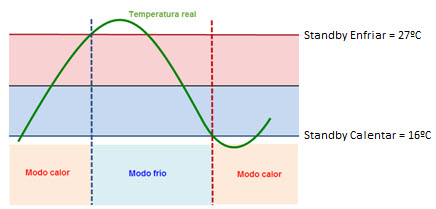
In Building Thermostat, values of setpoints of special modes have a limitation: Comfort, Standby and Economy setpoints should be established according to bands. In addition, the automatic change of mode is caused by variation of real temperature compared with setpoint temperatures of the current Special Mode in Heating and Cooling mode. This avoids undesired automatic changes of mode when a special mode or setpoint temperature changes.
My thermostat always uses 25 ºC as the reference temperature.
The Building thermostat module is independent of the device and it does not use the value measured by the internal temperature probe as the reference temperature by default. It is necessary to create one group address to link the “Temperature Source” object of the thermostat to the sending object of the internal temperature probe or other KNX probe.
Is it possible to do a presence simulation with InZennio Z38i or Roll-ZAS?
InZennio Z38i and Roll-ZAS have a presence simulator function that uses a 1-bit object to switch on/off a circuit during random periods of time within a specified time range parameterizable in ETS.
Besides this control, InZennio Z38i and Roll-ZAS timers allow the final user to set the on and off time of a circuit simulating the presence function.
How does Presence Simulation work?
When parameterizing any of the HOME or HOME II boxes in the Panel as "Presence Simulation" or this function is activated in Roll-ZAS, 2 new Communication Objects will appear in the ETS parameterization environment:
1.- "Presence Simulation" (1 bit) -> Enable/Disable the function
2.- "Simulation Channel" (1 bit) -> Generate the ON/OFF
It will be necessary in this case to create a group address (ie "Simulation") to be linked with the "Simulation Channel" Communication object in the InZennio and also with the corresponding objects in the devices to send the ON/OFF orders randomly.Having done that, the parameterization page in the ETS allows us to set the "Starting Time" and the "Finish Time" of the Simulation as well as setting the min & max ON/OFF times of the devices.
Once the “Presence Simulation” function is enabled , “0” & “1” will be randomly sent within the previous range set by parameter.
Zennio, Innovation and Versatility
Our products are innovative and versatile. Several products in our catalogue offer the possibility to download on them different Application Programs depending on the funcionality required in the installation.
A brief summary of the possibilities is shown next:
Ref: "ZN1VI-TP38" Touch Panel Z38
- InZennio Z38 -> Panel with tactil display, ambient thermostat, IR receiver and binary inputs.
- IRSC Test -> Application developed to simulate the operation of an Air Conditiong split unit showing on the Z38 display the status information. This way, integrators can test the IRSC performance without phisically having a Split unit.
Ref: "ZN1VI-TP38i" Touch Panel Z38i
- InZennio Z38i -> Panel with tactil display, ambient thermostat, IR receiver and binary inputs.
- IRSC Test -> Application developed to simulate the operation of an Air Conditiong split unit showing on the Z38 display the status information. This way, integrators can test the IRSC performance without phisically having a Split unit.
- IRSC Open Capture ->Application specifically developed to capture infrared frames from IR remote controllers.
Ref:"ZN1VI-TPZAS" touch controller ZAS
- ZAS -> This application groups the functionality of the controller in a Menu, which is divided in several submenus (Thermostat, Security, Scenes, etc.). It is possible to configure the functionality of up to 8 buttons in total, which carry out different actions, according to the ETS configuration.
- Roll-ZAS -> Add even more versatility to the room controller. The information is divided into pages (up to a total of 4 direct-action button pages, besides specific pages, such as Security, Configuration, etc.). In every button page, it is possible to configure up to 8 buttons (32 buttons in total), which will carry out different actions, according to the ETS configuration.
Ref: "ZN1IO-AB40" ActinBox QUATRO
- ACTinBOX QUATRO -> KNX Actuator combining 4 x 16A multifunction binary outputs (individual or shutter channel) with multioperation logical functions
- ACTinBOX QUATRO Fan Coil Controller -> Application developed to control 2 pipe Fan Coils.
Ref: "ZN1IO-AB60" ActinBox MAX6
- ACTinBOX MAX6 -> KNX Actuator combining 6 x 10A multifunction binary outputs (individual or shutter channel) with multioperation Logical Functions
- ACTinBOX MAX6 Fan Coil Controller-> Application developed to control 2 or 4 pipe Fan Coils + 1 General purpose output
Ref: " ZN1DI-RGBX3" Lumento X3
- LUMENTO X3 RGB -> joint control over one tricolor (RGB) LED module.
- LUMENTO X3 LED -> independent control over up to 3 monocolor LED modules.
Ref: " ZN1DI-RGBX4" Lumento X4
- Lumento X4 RGB -> joint control over one LED module of 4 colors (RGBW).
- Lumento X4 LED -> independent control over up to 4 monocolor LED modules.
- Lumento X4 WHITE -> control over two WHITE LED modules of 2 channels (warm white and cold white).
Ref: "ZN1CL-IRSC" IRSC
- IRSC Plus -> Designed to control Air Conditioning Systems with an IR receiver, including splits, ducted units with IR interface, or those to which one can be adapted.
- IRSC Zone -> Application Program specifically developed to control Air ducted zoning systems (up to 8 zones) con grilles and/or motorized gates.
- IRSC Open -> Application specifically developed to carry out an IR control via the KNX system. After analyzing theorders emitted by the infrared remote control, these orders can be send from any device in the KNX installation.
Ref: "ZN1RX-SKXOPEN" SKX-OPEN
- SKX Open -> Allow controlling devices with a RS232 port via KNX. Basic funcionality offers "1 bit" objects and a maximum frame length of "10 bytes".
- SKX Advance -> Allow controlling devices with a RS232 port via KNX. Advanced funcionality offers "1 bit", "1 byte" and "14 bytes" objects and a maximum frame lenght of "29 bytes".
Ref: "ZN1IO-KES" KES
- KES 3xSingle-Phase -> Allow monitoring up to 3 single-phase electrical circuits independently.
- KES 1xThree-Phase ->Allow monitoring 1 three-phase electrical circuit.
Inputs number and type of each Zennio device.
Zennio devices have two input types :
- Binary inputs: to connect push buttons/switches.
- Analog-digital inputs: to connect motion sensors or temperature probes. Also configurable as binary inputs.
Product | Binary inputs | Analog-digital inputs |
Z41 Lite | - | 2 |
Z41 Pro | - | 2 |
Z35 | - | 4 |
Roll-ZAS | - | 2 (no configurable as puss button) |
ZAS | - | 2 |
InZennio Z38i | 4 | - |
InZennio Z38 | 4 | - |
TMD Plus | - | 2 |
TMD | - | 2 |
TMD-Display One | - | 2* |
TMD-Display View | - | 2* |
Square TMD-Display | - | 2* |
Square TMD | - | 2 |
Flat 55 Display | - | 2 |
Flat 55 X1/X2/X4 | - | 2 |
Flat 1/2/4/6 | - | 2 |
Flat Display | - | 2 |
MAXinBOX 66 | - | 6 |
MAXinBOX 66 v2 | - | 6 |
MINiBOX 25 | - | 5 |
MINiBOX 25 v2 | - | 5 |
MINiBOX 45 | - | 5 |
inBOX 24 | - | 4 |
ACTinBOX CLASSIC HYBRID | 4 | Input 5: Temperature probe. |
ACTinBOX CLASSIC | 6 | - |
DIMinBOX 2CH | - | 2 |
DIMinBOX DX2 | - | 2 |
Lumento DX4 | - | 6 (No configurable as probe) |
MAXinBOX FC 0-10 V FAN | - | 4 |
MAXinBOX FC 0-10V VALVE | - | 4 |
MAXinBOX Hospitality | - | 6 |
QUAD | - | 4 |
RailQUAD | - | 8 |
BIN 2X | 2 | - |
BIN 4X/44 | 4 | - |
*Inputs not available for luminosity sensor functionality.
What does safe mode mean?
When a device is running in safe mode the programming LED blinks in red, meaning that the application program is halted.
How to set a device in safe mode?
To activate the safe mode, keep the programming button pressed while connecting the device into the KNX bus. This process is described in the datasheet of the device.
How to exit from safe mode?
To exit from safe mode, simply plug the KNX bus into the device but do not press the programming button this time. This way the programming LED does not blink, meaning that the application program is running (safe mode is not active).
How do a download in safe mode?
When an incidence is caused during the download, it is recommended to do a safe mode download, to ensure that the previous corrupted download doesn’t affect to this new download:
To do a download in safe mode, you should follow the next steps:
- Disconnect the device from KNX bus.
- Connect the device to KNX bus while holding down the programming button. The programming LED will start blinking indicating that the device is in safe mode.
- Once in safe mode, download the application program completely to the device.
- When the download is finished, disconnect and reconnect the device from the bus.