English
 Español
 Français
 Deutsch
What is the difference between InZennio Z41 and Z41 Pro/Lite?
Z41 Pro/Lite are the new models that replace InZennio Z41 in our catalogue from now on. The 3 devices are physically equal (excepting Z41 Pro/Lite include 2 analog-digital inputs), but starting from the application program version 2.2, Z41 Pro/Lite have been improved with new important functionality such as twelve general-purpose control pages, holiday calendar, water and gas monitor, four-byte indicators, new specific fan speed control, error log, light intensity regulation on RGB/RGBW controls... For further information, see the Z41 Pro or Z41 Lite manual.
Moreover, Z41 Pro allows IP connection for smartphone/tablet control with Z41 Remote app (available for iOS and Android) in the same way as InZennio Z41. However, dinamic IP is necesary for both devices to connect to IP network.
The application program available on the website is only valid for ETS4 or ETS5, is there a compatible version with ETS3?
No, the application program developed for the Z41 is only compatible with ETS4 or ETS5.
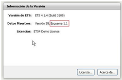
I cannot import the application program for the Z41, the ETS4 shows the message “The version of the Scheme is not valid", what can I do?
To import the application program for the Z41 is necessary to have the ETS4 software updated with a version of "Scheme" 1.1 or higher. You can view this information from the main screen of the ETS4, in the Overview section. The version information is displayed in the upper right corner.
May I install the Z41 horizontally?
Yes, from the Z41 Pro/Lite 2.3 versions and Z41 COM 1.1, this touch panels may be installed horizontally or vertically. On the other hand, InZennio Z41 can't be installed horizontally
May I use the KNX bus voltage (29VDC) as the additional power supply of the Z41?
No, the KNX bus voltage is not a clean signal as it is modulated by the data. This signal can cause a malfunction of the screen.
The KNX bus connector and the external power supply connector are opto-isolated to avoid potential interference with the KNX bus.
Do I need an additional KNX power supply as external power supply for the Z41?
No, the auxiliary power supply does not need to be a KNX power supply, a conventional power supply (12-29V DC), or the auxiliary output of some KNX power supplies is enough.
What is the total consumption of the Z41?
The consumption of the Z41 is divided as follows:
- KNX Bus: 6 mA
- External power supply: the maximum consumption at startup is 160 mA (with 12 V), 76 mA (with 24 V) or 64 mA (with 29 V), but in standby, its consumption is reduced to about half of this figure.
It can be checked in the Z41 datasheet
What is the firmware of the Z41?, and how can I update it?
We call firmware to the base software preloaded on the device that handles the display of all items on the screen. The firmware is independent of the ETS application program, but both must be the same version for the Z41 to work properly.
The firmware update must be performed via the miniUSB port or the Ethernet port:
- Via USB: using the adapter cable for USB firmware update connected to the mini-USB port placed on the back of the touch screen. The “.PAK” file for firmware update must be copied to the root folder of a USB flash drive.
- Via Ethernet: Downloading de Z41 Update tool and connecting the touch panel to be updated and the computer to the same local network. Z41 Lite cannot be updated via Ethernet
Both procedures are explained step by step in the firmware update manual
Should I update first the firmware or the software?
Even though it can be done in both ways, from Zennio we recommend to update firstly the firmware version, and secondly the application program.
The screen stays with blue background and it displays an “Error Software” message. What is going on?
The “Error Software” message means a wrong correspondence between Software and Firmware versions.
Software version X.Y must match with the firmware version X.Y.Z. The versions will be compatible when X.Y values are equal.
What is the Ethernet input for?
The Ethernet port built into the Z41 may be used to upgrade its firmware, and for the remote controlling of the Z41 via IP from devices such as smartphones or tablets.
How can I know the Z41 MAC number?
The MAC is displayed on the screen when the touch panel is in the firmware update state.
It is also possible to know it by running the command “arp-a” in the command shell (cmd) of a computer connected to the same network.
If a power failure occurs, do I need to re-set the date and time?
No, thanks to the button battery included in the Z41, the touch panel allows to keep the date and time data after a power failure.
When are the date and time of the Z41 sent to the BUS?
The Z41 Touch Panel only sends the date and time data to the BUS when these two options are set, more specifically when the SET button is pressed, at the end of the manual parameterization.
This feature allows synchronizing the date and time of the rest of Panels in the installation by creating two group addresses “Date” and “Time” to later link them with the appropriate communication objects in the rest of panels to synchronize; this way when adjusting date and time in one of the "master" panels, the rest of them will be also updated.
When having several touch screens Z41 in the same installation, How is recommended to configure the time/date sending period?
It is necessary to configure just one screen in the installation to send time and date periodically to the bus, disabling in the remaining devices the parameter “Time/Date Sending Period” that can be found at MAIN CONFIGURATION/ General.
What alphabets can be displayed on the Z41?
Z41 is able to show the following alphabets:
- Latin
- Greek
- Cyrillic
- Arabian
- Hebrew
- Chinese
- Japanese
Is it possible to disable the temperature and time displayed at the top of the screen?
Yes, it is possible to disable the display of this information through the GENERAL setting parameters independently.
Can I show a temperature value different from the one measured by the internal sensor in the header of the screen?
This is possible by enabling this option in the GENERAL setting parameters.
How can I display the values received in an indicator control over time?
It is possible to save a log of the values received in indicator controls of 1 or 2 bytes simply by enabling this option via the "Save Log?" parameter. Then, pressing on the indicator will open a pop-up window that will display graphically the values received in this indicator over time.
I have configured an “Energy Monitor” control to display the energy consumption and the objects that I need to link with my energy monitor do not appear. I can only see the objects “Energy Monitor: request” and “Energy Monitor: reset”, why?
To use this “Energy Monitor” control in Z41 Pro/Lite 1.1, it is necessary to enable the monitoring channels via the “Energy Monitor Objects” tab that you will find in the MAIN CONFIGURATION section. For each channel, four objects will be created: “Power”, “Energy”, “CO2” and “Cost Estimation”.
Starting from the 2.2 version, it is not necessary to enable the channels since these functions are enabled in each box configuration.
I have configured a 2-button control and the value sent by each button does not correspond to its icon. What’s happening?
When configuring the 2-button control, it must be taken into account that the icon selection parameter does not assign functionality to the button. The icon is independent of the value sent. All the 2-button controls have a parameter called "Action" that allows exchanging the value sent to the bus between the left and right buttons.
Why when playing Scene nº X, the Group Monitor always show a minor number X-1?
This is due to the particular structure of the "Scenes Control" DPT. For further information, consult the Scenes Example Project.
How many Group Addresses do I need to work with Scenes?
One only Group Address will be needed to work with scenes.
Every device involved in the Scene has a specific Communication object "Scenes". It will only be necessary to link this with the "Scenes" Communication Objects in the devices involved in the predefined atmosphere. For further information, consult the Scenes Example Project.
Is it possible to show the current scene in the display?
Scenes are events, not status; while setting a scene, some predefined parameters are set in the devices involved in the same, however these can be later modified by the users.
How can I learn scenes with the display?
Guess a user defines the "Scene Night" (programming the Panel with parameters and group addresses via ETS) to:
- Turn all the lights Off
- Turn Off the Heating and the AC system
- Activate the Alarm System
Once the scene is defined, every time we play it, a predefined atmosphere is generated.
Afterwards, the user wants this configuration instead:
- Turn all the lights Off except one (the one to remain ON, will be a guiding light)
- Turn Off the Heating and the AC system
- Activate the Alarm System
The way to do this is:
1. Run the scene to be modified.
2. Turn the light we want it to be the guiding light On.
3. Just save the new scene into the Panel by keeping a long press (3 seconds) on the original scene "Run" button.
THIS PROCESS REPLACES THE ORIGINAL SCENE BY THE MODIFIED ONE
Which Zennio devices include binary inputs?
You can check which Zennio devices have binary (digital) inputs in the following table
Differences between Push button and Switch/Sensor inputs
A push button connected to an input consists of a device, which allows, or not, the current flow while this is being pushed; in normal conditions, push buttons contacts are always open (NO) or closed (NC). This event is a pulsation and the time it lasts, threshold time. Depending on the “Threshold Time” it can be distinguished two different actions:
- Short press
- Long press
A Switch/Sensor connected to an input, consists of an electrical mechanism which may have its contacts open or closed under normal conditions. These mechanisms don’t recover their normal position automatically as with the push button. A transition of a digital signal from low/high/low is called "Edge".
- Falling edge: Closed contact to Open Contact.
- Rising edge: Open contact to Closed Contact.
What type of contacts can be connected on the binary inputs?
Binary inputs of Zennio devices are voltage free contacts. They can be individually configured and each of them can be connected to a push buttons and/or a switch/sensors.
Can I connect several push buttons in parallel in the same input?
Yes, inputs are voltage free, so there is no problem in connecting several push buttons in parallel.
Why do I have to press twice over an input for the output to react?
It happens when one output is commuted by two or more different inputs and the output status object isn't used to synchronize these inputs.
What is the maximum length allowed for the wiring of the digital inputs?
The wiring of the digital inputs can be extended up to 30 meters using a cable with a section between 0.15 mm2 and 1 mm2.
I have several scenes scheduled to be launched at the same time and only one is launched, why?
Due to the fact that the scene object is unique to the entire touch panel, it is only possible to launch one scene at a time, more precisely, the scene launched will be the one set in the last box of the last page. To avoid this effect, the sending of the scenes can be shifted in time.
How can I schedule a Climate System timer?
1. Configure one Z41 box as "chronothermostat" (Visualization: Other --> Function: Chrono-thermostat)
2. Three group objects will be generated:
- [Px][By] Chrono-thermostat: enabling - Link to a binary object to enable/disable the chronothermostat function
- [Px][By] Chrono-thermostat: temperature setpoint - Link to the thermostat setpoint object
- [Px][By] Chrono-thermostat: on/off - Link to the thermostat on/off object
Note: it is not obligatory to link these 3 group object if you don't want to control any of these functions by means of chronothermostat
3. In the corresponding Z41 box, set the time and setpoint to which you want to set the climate system
What is the difference between motion detectors P (ZN1IO-DETEC-P) and X (ZN1IO-DETEC-X)?
The only difference is that the motion detector P has a built-in luminosity sensor and it allows to constraint the detection based on the luminosity level detected in the room. The motion detector X has no luminosity sensor.
Can I connect a motion sensor different from DETECT-P/X to an device input configured as motion sensor?
Zennio devices with inputs configurable as sensor motion have been designed to work together with the motion sensor DETEC-P and DETEC-X
We can’t guarantee the proper working of a different motion sensor connected to a Zennio device input configured as motion sensor, thus, when using a different motion sensor, the input must be configured as binary switch, and the sensor motion must send the detection using a free potential contact.
To which Zennio devices can I connect a motion detector?
Motion detectors can be connected to Zennio devices with analog-digital inputs.
If you do not know if your Zennio device allows the motion detector connection, just look into the following table. For further information, consult the product datasheet.
If the device allows the connection of a motion sensor, at its website tools section you will find the motion sensor manual.
How can I know the position where the micro switch must be placed (Type A/B)?
Depending on the device where the motion sensor is connected, the micro switch must be placed at the position A or B. To know which position corresponds to your device, it is necessary to check the device datasheet to which the motion sensor will be connected.
How many sensors can I connect into the same input?
Up to two different sensors can be connected in parallel to the same motion sensor input, as long as at least one of them has the luminosity sensor switch in the OFF position. This is achieved using the micro-switch located on the back of the device. For further information please refer to the motion sensor datasheet.
Do I need an external power supply for the sensor?
No, you just need to connect it to the inputs of the devices allowing its control
What is the detection area covered by a Zennio motion sensor?
This feature depends critically on the location of the device. In particular, for a detector located in the ceiling of a room, the detection area can be doubled if you double the height at which it is placed. For further information, consult the motion sensor datasheet.
How should I install the motion sensor to get the most of its functionality?
In the Motion Sensor area, you can download the Installation Note that includes installation tips to find the most suitable place to be placed.
How is the luminosity level measured by the sensor sent to the bus? (Only ZN1IO-DETEC-P)
The sensor sends a luminosity level in the range [1.....100] through a 1 byte Communication Objet. In any case this is a a 2 bytes object with the value measured in LUXES.
Can we cancel the LED blinking everytime there is a detection?
Yes, using the micro switch at the rear of the device.
What is the maximum length allowed for the wiring of the analogue inputs?
The wiring of the analogue inputs can be extended up to 30 meters using a cable with a section between 0.15 mm2 and 1 mm2.
The luminosity sensor does not measure correctly. (Only ZN1IO-DETEC-P)
Check if the microswitch number 2 is placed in the correct position. You can find this information in the data sheet of the device to which it is connected.
Is it possible to do a presence simulation with Z41?
Z41 does not have that specific function; however, a similar functionality can be created by programming weekly and daily timers, and setting different sequences to simulate presence. In addition, Z41 allows users the remote control through smartphone and tablet, having the full control of the installation.
To which Zennio devices can I connect a temperature probe?
Temperature probes can be connected to Zennio devices with analog-digital inputs. To know if a device has analog-digital inputs, look into its datasheet.
In the following table you can check all Zennio devices with analog-digital inputs
What is the max cable length of the temperature probes?
The probe cable length provided by Zennio is 1.5 meters, however, this can be enlarged by means of a cable with similar characteristics up to a maximum of 30 meters.
What is the resistance value of the temperature probe at 25°?
The resistance value at 25°C is 6,8 kΩ
What are the valid measurement ranges for the temperature probes?
The following ranges are valid for the probes:
- Epoxi probe: [-30ºC........+90ºC]
- Steel probe: [-30ºC........+125ºC]
What is the appropriate probe in my installation?
It depends on the desired temperature range and the place where the probe will be placed.
As described in the previous question, steel probes have a broader range of measurement and are ready to work in more extreme environments than epoxy probes.
What is the temperature probe precision when it is used in QUAD?
It has a precision of +/- 0,5 °C
Can I use temperature probes different from the supplied by Zennio?
Zennio devices were designed to operate according to the characteristics of our temperature probes. We can only guarantee the proper working of the device with Zennio probes.
Exceptionally, other NTC temperature probes can be used with RailQUAD and QUAD Plus (from version 1.1 of both devices) since it is possible to configure the parameters of the characteristic curve of a NTC probe in this application program
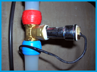
How can I install a temperature probe into a narrow plastic pipe?
Use a T-shaped piece, take advantage of the new outlet to install a thermowell and now you will be able to place inside our steel temperature probe ZN1AC-NTC68S.
How can I hide the ambient temperature probe on the wall?
Install a conventional mounting box and uses a cable outlet cap. Place the temperature probe so that only its measuring end is seen. In this case we recommend using our epoxy resin probes ZN1AC-NTC68E and ZN1AC-NTC68F.
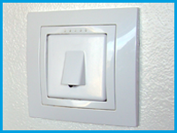
Moreover, SQ-AmbienT has been designed to meeting this need, a temperature probe installed in a Square family panel that provide an minimalistic aesthetic to the installation
What is the Technical Alarm Cyclical Monitoring used for?
This function allows a critical alarm system monitoring (i.e. gas sensor) to check its proper working in the installation.
In this case, the function waits for a value reception to confirm that the system is working properly. If this value is not received within the specific time parameterized in the ETS, the alarm goes off warning users of a possible problem in the device.
Climate "MODE" Communication object structure in Z41 Touch Panel.
This communication objet (DPT_HVACContrMode_20.105) fulfillls the KNX standard with the following structure:
0 = AUTO
1 = HEAT
3 = COOL
9 = FAN
14 = DRY
This DPT structure is actually implemented in all the Zennio devices. This way, all the devices can be integrated together in an installation, as their Communication Objects structure is identical. For further info, please contact our Technical Department.
What is the Special Mode control of the Z41 for?
The Special Mode control is used to set pre-configured setpoints in the thermostat. For further information about this functionality, see the manual of the “Building” thermostat.
Can I restrict the setpoint temperatures in public buildings with the Z41?
Yes, the Z41 temperature controls allow restricting the range of allowed values.
The internal temperature sensor of the Z41 shows a higher temperature value than the real one, Why?
The Z41 usually gets hot during its programming in such a way that the real temperature is distorted during this time period. The Z41 will recover the real temperature once it returns to its standby status.
Furthermore, supplying the Z41 with a voltage value or another can cause variations in the measurement of the temperature; however, the temperature displayed is automatically calibrated by selecting the “Power Supply Voltage” parameter properly.
Additionally, the internal temperature sensor can be calibrated manually from the ETS setup or from the configuration page.
Can the temperature measured by the internal sensor of the Z41 be sent periodically to the bus?
Yes, within the parameters of the Z41, it is possible to choose a cyclic sending period of the temperature measured by the internal sensor with a range between 10 and 1000 s.
What is the welcome object for?
The welcome object can be used to send a binary value to the bus or to launch a scene, the first time that the touch panel is pressed after a configurable time of inactivity. This object can be very useful to turn a light on or to launch a welcome scene.
What is the locking for?
The lock object allows enabling or disabling the touch area of the Z41, so that if the screen is locked, it ignores any press on it until it is unlocked. This object may be useful to disable touch panels installed in public areas.
Inputs number and type of each Zennio device.
Zennio devices have two input types :
- Binary inputs: to connect push buttons/switches.
- Analog-digital inputs: to connect motion sensors or temperature probes. Also configurable as binary inputs.
Product | Binary inputs | Analog-digital inputs |
Z41 Lite | - | 2 |
Z41 Pro | - | 2 |
Z35 | - | 4 |
Roll-ZAS | - | 2 (no configurable as puss button) |
ZAS | - | 2 |
InZennio Z38i | 4 | - |
InZennio Z38 | 4 | - |
TMD Plus | - | 2 |
TMD | - | 2 |
TMD-Display One | - | 2* |
TMD-Display View | - | 2* |
Square TMD-Display | - | 2* |
Square TMD | - | 2 |
Flat 55 Display | - | 2 |
Flat 55 X1/X2/X4 | - | 2 |
Flat 1/2/4/6 | - | 2 |
Flat Display | - | 2 |
MAXinBOX 66 | - | 6 |
MAXinBOX 66 v2 | - | 6 |
MINiBOX 25 | - | 5 |
MINiBOX 25 v2 | - | 5 |
MINiBOX 45 | - | 5 |
inBOX 24 | - | 4 |
ACTinBOX CLASSIC HYBRID | 4 | Input 5: Temperature probe. |
ACTinBOX CLASSIC | 6 | - |
DIMinBOX 2CH | - | 2 |
DIMinBOX DX2 | - | 2 |
Lumento DX4 | - | 6 (No configurable as probe) |
MAXinBOX FC 0-10 V FAN | - | 4 |
MAXinBOX FC 0-10V VALVE | - | 4 |
MAXinBOX Hospitality | - | 6 |
QUAD | - | 4 |
RailQUAD | - | 8 |
BIN 2X | 2 | - |
BIN 4X/44 | 4 | - |
*Inputs not available for luminosity sensor functionality.
What does safe mode mean?
When a device is running in safe mode the programming LED blinks in red, meaning that the application program is halted.
How to set a device in safe mode?
To activate the safe mode, keep the programming button pressed while connecting the device into the KNX bus. This process is described in the datasheet of the device.
How to exit from safe mode?
To exit from safe mode, simply plug the KNX bus into the device but do not press the programming button this time. This way the programming LED does not blink, meaning that the application program is running (safe mode is not active).
How do a download in safe mode?
When an incidence is caused during the download, it is recommended to do a safe mode download, to ensure that the previous corrupted download doesn’t affect to this new download:
To do a download in safe mode, you should follow the next steps:
- Disconnect the device from KNX bus.
- Connect the device to KNX bus while holding down the programming button. The programming LED will start blinking indicating that the device is in safe mode.
- Once in safe mode, download the application program completely to the device.
- When the download is finished, disconnect and reconnect the device from the bus.